best car to learn manual

Mastering a manual transmission offers greater control, connection with the car, and improved driving skills. Popular models like the Honda Civic and Mazda MX-5 Miata are ideal for beginners, providing smooth shifts and forgiving clutches. Learning to drive a stick shift opens up a world of vehicle options and is a rewarding skill for any driver.
1.1 Why Learning Manual Transmission is Beneficial
Mastering a manual transmission offers numerous advantages for drivers. It provides better fuel efficiency, as manual cars typically consume less fuel compared to automatics. Additionally, manual vehicles are often more cost-effective to purchase and maintain. Driving a manual car also enhances driver engagement, offering a more connected and enjoyable driving experience. Furthermore, manual transmissions give drivers greater control, especially in challenging conditions like hills or rough terrain. Learning to drive a manual is a valuable skill that broadens car ownership options and is highly regarded among driving enthusiasts. It also fosters better understanding of vehicle mechanics and improves overall driving proficiency. With practice, the ability to handle a manual transmission becomes second nature, making it a worthwhile investment of time and effort for any driver.
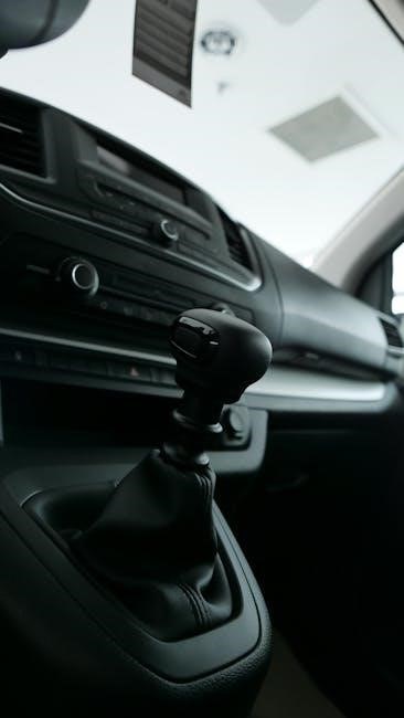
1.2 Key Components of a Manual Car
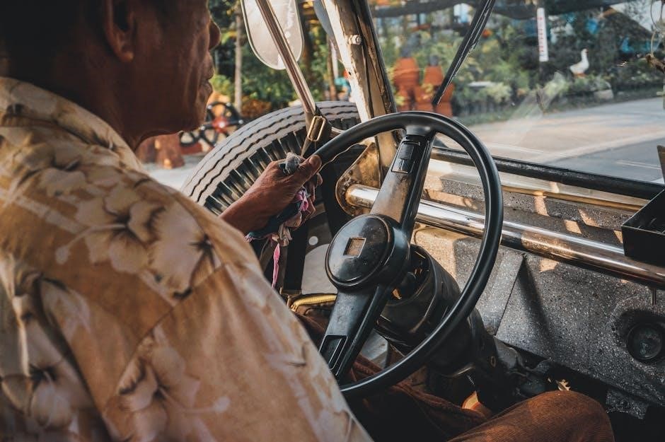
A manual car consists of several essential components that work together to enable driver control. The clutch pedal, located on the far left, disengages the engine from the transmission, allowing gear changes. The gearshift, typically located on the center console or floor, is used to select the desired gear. The transmission itself houses the gears that transfer power to the wheels. Other critical parts include the flywheel, pressure plate, and release bearing, which assist in smooth clutch operation. Understanding these components is vital for effective learning, as they directly impact how the car responds to driver input. These elements work in harmony to provide precise control over acceleration and deceleration, making manual driving both engaging and efficient. Familiarizing oneself with these parts is the first step in mastering manual transmission driving.
Factors to Consider When Choosing a Car for Learning Manual
Key considerations include smooth gear shifts, forgiving clutch engagement, lightweight design, and manageable engine size. These factors ensure an easier and less intimidating learning experience for beginners.
2.1 Smooth Gear Shifts and Clutch Engagement
Smooth gear shifts and clutch engagement are critical for an enjoyable learning experience. A car with a responsive clutch and seamless shifting allows learners to focus on mastering the balance between the clutch and accelerator. Vehicles like the Honda Civic and Mazda MX-5 Miata are praised for their smooth, forgiving clutch systems, making it easier to avoid stalling and coordinate gear changes. A well-tuned transmission reduces the intimidation factor, enabling new drivers to build confidence. Additionally, a light clutch pedal and precise gearshift action minimize fatigue during practice sessions. These features are essential for learners, as they help develop muscle memory and improve coordination between the clutch and accelerator pedals. A smooth system also reduces the risk of wear and tear on the clutch, making it a practical choice for extended practice periods;
2.2 Lightweight and Forgiving Vehicles
Lightweight and forgiving vehicles are ideal for learning manual transmission, as they minimize the risk of stalling and reduce the strain on the clutch. Cars like the Mazda MX-5 Miata and Honda Fit are excellent choices due to their compact size and responsive handling. These vehicles are easier to maneuver, allowing learners to focus on mastering clutch control and gear shifts without the intimidation of a heavier car. A lighter car also tends to have a smoother acceleration, making it less likely to stall during practice. Forgiving vehicles are more patient with mistakes, giving new drivers the confidence to practice without the fear of damaging the car. This makes them perfect for honing skills in a stress-free environment. Their ease of handling ensures a positive learning experience, helping drivers progress from novices to confident manual operators.
2.4 Reliability and Maintenance Costs
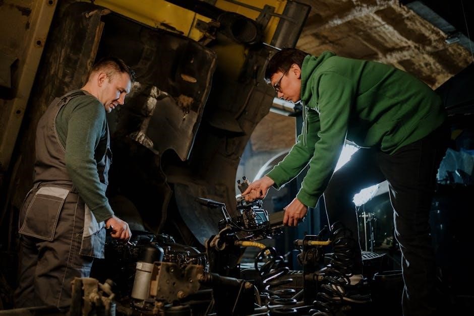
Reliability and maintenance costs are crucial factors when selecting a car for learning manual transmission. A reliable vehicle ensures consistent performance, reducing the likelihood of unexpected breakdowns during practice. Cars with lower maintenance costs are ideal, as they minimize financial stress while mastering the skill. Models like the Honda Civic, Mazda MX-5 Miata, and Toyota Corolla are praised for their durability and affordability. These cars are less prone to expensive repairs and offer a cost-effective learning experience. Additionally, their straightforward mechanical designs make them easier to maintain and repair, which is beneficial for new drivers who may occasionally stall or mishandle the clutch. Prioritizing reliability and lower maintenance costs allows learners to focus on improving their driving skills without worrying about frequent or costly repairs, making the learning process more enjoyable and stress-free.
Top Cars for Learning Manual Transmission
Popular models like the Honda Civic, Mazda MX-5 Miata, and Toyota Corolla are ideal for learners due to their smooth gear shifts, forgiving clutches, and proven reliability, making them perfect for mastering manual driving skills.
3.1 Honda Civic (Older Models)
The Honda Civic, particularly older models, is a standout choice for learning manual transmission. Known for its reliability and ease of use, the Civic offers smooth gear shifts and a forgiving clutch, making it ideal for beginners. Its lightweight design and responsive handling provide a perfect balance for mastering clutch control and acceleration. Additionally, older Civics are often more affordable and widely available, making them accessible for new learners. The simplicity of its manual gearbox ensures a straightforward learning experience, while its fuel efficiency adds practicality. Many drivers have successfully learned to drive a manual transmission using the Civic, praising its intuitive feel and durability. Whether you’re practicing in a parking lot or navigating city streets, the Honda Civic is a reliable companion for mastering the art of driving a manual car.
3.2 Mazda MX-5 Miata
The Mazda MX-5 Miata is a highly recommended car for learning manual transmission due to its smooth, precise gear shifts and lightweight design. Its rear-wheel-drive layout provides a responsive driving experience, making it easier for beginners to feel connected to the road. The Miata’s forgiving clutch and intuitive handling allow learners to practice without the stress of stalling frequently. Its compact size and excellent visibility also make it a great choice for navigating tight spaces and practicing low-speed maneuvers. Additionally, the Miata is known for its reliability and affordable maintenance costs, making it a practical option for new drivers. The car’s sporty yet approachable nature ensures that learners can build confidence while enjoying the process of mastering manual transmission. With its balanced performance and ease of use, the Mazda MX-5 Miata is an excellent vehicle for anyone looking to learn how to drive a stick shift.
3.3 Ford Mustang (Pre-2010 Models)
The Ford Mustang, particularly pre-2010 models, is a popular choice for learning manual transmission due to its classic design and straightforward mechanics. These models offer a smooth clutch engagement and a gearing system that is forgiving for new drivers. The Mustang’s rear-wheel-drive layout and strong engine provide a responsive yet manageable driving experience, allowing learners to practice shifting gears without the complexity of modern technology. Additionally, the Mustang’s iconic status and relatively affordable maintenance make it a great option for those looking to practice without worrying about high costs; Its strong community support and availability of parts also add to its appeal. With its balance of power and simplicity, the Ford Mustang is an excellent vehicle for mastering manual transmission and building confidence behind the wheel.
3.4 Toyota Corolla (Manual Models)
The Toyota Corolla, especially in its manual models, is a reliable and practical choice for learning manual transmission. Known for its smooth clutch engagement and consistent gear shifts, the Corolla offers a forgiving platform for new drivers. Its lightweight design and responsive handling make it easy to maneuver, reducing the frustration often associated with learning to shift gears. The Corolla’s reputation for durability and low maintenance costs also makes it an excellent option for learners who may stall or ride the clutch frequently. Additionally, its fuel efficiency and compact size make it a great city car for practice. With its straightforward mechanics and user-friendly nature, the Toyota Corolla is an ideal vehicle for building confidence and mastering the basics of manual transmission without the intimidation factor of more powerful cars.
Tips for Learning Manual Transmission
Start in a flat, open area to practice clutch control and smooth shifting. Focus on balancing the clutch and accelerator for seamless gear changes. Be patient and persistent to master the skill.
4.1 Finding a Safe Practice Location
Finding a safe and suitable location is crucial for learning manual transmission. An empty parking lot or a flat, open space away from traffic is ideal. Avoid steep inclines or busy streets to minimize stress. Ensure the area is free from obstacles and distractions, allowing you to focus on mastering clutch control and gear shifts. Starting on flat ground helps you get accustomed to the clutch and accelerator balance without the added challenge of inclines. Practicing in a quiet, low-pressure environment reduces the risk of stalling and makes the learning process more enjoyable. Always choose a location where you can safely stop and restart without causing disruption. Patience and a good practice spot are key to becoming proficient in manual driving.
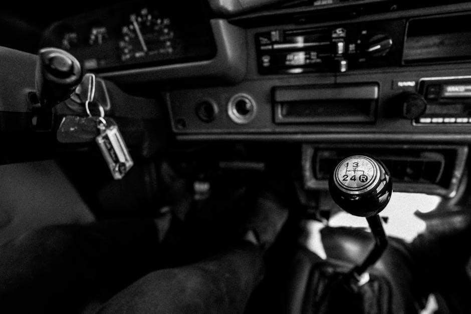
4.2 Mastering the Clutch and Accelerator Balance
Mastering the balance between the clutch and accelerator is essential for smooth gear transitions. Start by slowly releasing the clutch while gently pressing the accelerator to feel the “biting point” where the engine begins to engage. Practice in first gear on a flat surface, gradually lifting the clutch while applying light throttle. Avoid sudden movements, as they can cause jerking or stalling. With time, you’ll develop a sense of when to ease off the clutch and when to press the accelerator to maintain momentum. This balance is crucial for seamless shifting and preventing wear on the clutch. Consistent practice in a controlled environment will help you perfect this technique, making manual driving feel natural and intuitive.
4.3 Common Mistakes to Avoid
When learning to drive a manual, avoid common pitfalls that can hinder progress. One of the most frequent mistakes is riding the clutch, which occurs when the clutch pedal isn’t fully released. This can cause unnecessary wear and tear on the clutch and lead to premature replacement. Another mistake is shifting gears too quickly or aggressively, which can result in jerky movements and potential stalling. Inexperienced drivers often forget to downshift before slowing down, which can reduce control and strain the brakes. Additionally, stalling the car is common, especially in the beginning, but it can be minimized by practicing in a safe, flat area without pressure. Lastly, avoid over-revving the engine when shifting gears, as this can damage the transmission and waste fuel. Being mindful of these mistakes will help you learn more efficiently and prolong the life of your car.
Additional Resources for Learners
Online tutorials, video guides, and driving schools specializing in manual transmission are excellent resources. These tools offer step-by-step instruction, practical tips, and personalized guidance to help learners master the skill effectively.
5.1 Online Tutorials and Video Guides
Online tutorials and video guides are invaluable for mastering manual transmission. Platforms offer step-by-step lessons, from basic clutch control to advanced shifting techniques. Videos provide visual demonstrations, making complex concepts easier to grasp. Many tutorials include troubleshooting tips for common mistakes, such as stalling or rough shifts. Additionally, interactive simulations allow learners to practice in a virtual environment, reducing the fear of damaging a real car. Websites like YouTube and specialized driving channels feature experienced instructors sharing practical advice. These resources are accessible anytime, making them ideal for self-paced learning. Combining online tutorials with hands-on practice ensures a comprehensive understanding of manual driving. They are a convenient and effective way to build confidence and skill behind the wheel.
5.2 Driving Schools Specializing in Manual
Enrolling in a driving school that specializes in manual transmission is a highly effective way to learn. These schools offer professional instructors with extensive experience in teaching stick-shift driving. Their structured programs are designed to build confidence and skill, covering everything from basic clutch control to advanced shifting techniques. Many schools use vehicles specifically chosen for their ease of use, such as the Honda Civic or Mazda MX-5 Miata, which are known for their smooth gear shifts and forgiving clutches. Instructors provide personalized feedback, helping learners overcome common challenges like stalling or rough transitions. Additionally, these schools often include practice sessions in safe, low-pressure environments, allowing learners to refine their skills without stress. For those seeking a guided and supportive learning experience, specialized driving schools are an excellent choice.
Mastering manual transmission opens up a world of driving freedom and enjoyment. Choosing the right car, like a Honda Civic or Mazda MX-5, makes the learning process smoother. Embrace the challenge, stay persistent, and enjoy the rewarding experience of driving a manual!
6.1 Final Thoughts on Choosing the Best Car
Selecting the right car to learn manual transmission is crucial for a smooth experience. Opt for models known for smooth gear shifts and forgiving clutches, such as older Honda Civics or Mazda MX-5 Miatas. These cars are well-suited for beginners due to their balanced performance and ease of handling. Avoid vehicles with overly complex or stiff clutches, as they can frustrate new learners. Reliability and maintenance costs are also important factors to consider, ensuring you can practice without worrying about frequent repairs. Ultimately, the best car for learning is one that makes the process enjoyable and stress-free, allowing you to focus on mastering the skill of driving a manual transmission.
6.2 Encouragement for New Learners
Learning to drive a manual transmission is a rewarding skill that takes time and patience. Don’t be discouraged by stalling the car—it’s a natural part of the learning process. Start in a safe, open space where you can practice without pressure. Celebrate small victories, like smoothly shifting gears or mastering the clutch-accelerator balance. Remember, consistency is key. The more you practice, the more comfortable you’ll become. Embrace the challenge and enjoy the journey of becoming a confident manual driver. The sense of accomplishment and the joy of driving a stick-shift car make every moment of practice worthwhile. Keep pushing forward, and soon you’ll be shifting gears like a pro!