automatic vs manual coffee machine
The debate between automatic and manual coffee machines centers on convenience versus control, impacting daily routines and the pursuit of the perfect brew․
The Growing Popularity of Home Coffee Brewing
The rise of home coffee brewing reflects a desire for quality, cost savings, and personalized experiences․ Consumers are increasingly seeking alternatives to daily coffee shop visits, driven by both economic factors and a growing appreciation for specialty coffee․ This trend fuels demand for both automatic and manual machines․ Articles highlight the appeal of café-quality drinks at home, reducing expenses․
The convenience of automatic machines attracts busy individuals, while manual methods appeal to those who enjoy a hands-on approach and flavor exploration․ This expanding market showcases a diverse range of options, catering to varied preferences and skill levels, solidifying coffee’s place as a daily ritual․
Defining Automatic and Manual Coffee Machines
Automatic coffee machines streamline the brewing process, handling most steps with minimal user intervention․ These range from simple drip machines to sophisticated bean-to-cup models and convenient capsule systems․ They prioritize ease of use and consistency, often featuring pre-programmed settings․ Conversely, manual machines require active participation from the user throughout the entire brewing cycle․
Methods like French press, pour-over, and lever espresso machines demand precise control over variables like grind size, water temperature, and brew time․ This hands-on approach allows for greater customization but necessitates skill and practice, offering a more involved coffee experience․
Understanding Automatic Coffee Machines
Automatic machines offer simplified brewing, encompassing drip, bean-to-cup, and capsule options, prioritizing convenience and consistent results for effortless daily coffee enjoyment․
Types of Automatic Coffee Machines
Automatic coffee machines cater to diverse preferences with several distinct types․ Drip coffee makers are the most common, offering straightforward brewing for larger batches․ Bean-to-cup machines grind beans just before brewing, maximizing freshness and flavor․
Capsule/pod machines provide ultimate convenience, utilizing pre-portioned coffee grounds for quick and consistent results, though potentially at a higher long-term cost․ Breville’s The Oracle Dual Boiler exemplifies a sophisticated automatic option, blending automation with manual control․ Each type balances ease of use with varying degrees of customization and expense, impacting the overall coffee experience․
Drip Coffee Makers
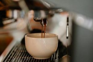
Drip coffee makers represent the quintessential automatic brewing method, prized for their simplicity and capacity․ These machines heat water and slowly drip it over a bed of ground coffee, filtering into a carafe below․ They are ideal for brewing larger quantities, making them suitable for families or offices․
While offering convenience, drip coffee makers generally provide less control over brewing variables like water temperature and saturation time․ They are a cost-effective entry point into automatic coffee brewing, though flavor complexity may be limited compared to other methods․
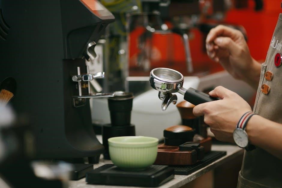
Bean-to-Cup Machines
Bean-to-cup machines offer a fully automated experience, grinding whole coffee beans immediately before brewing․ This preserves the coffee’s aroma and flavor, delivering a fresher cup compared to pre-ground options․ These machines handle everything from grinding and tamping to brewing and, in some cases, milk frothing․
While more expensive than drip machines, bean-to-cup models provide a significant upgrade in convenience and quality․ They often feature customizable settings for strength and volume, but can require regular cleaning and maintenance to ensure optimal performance․
Capsule/Pod Machines
Capsule or pod machines, like Nespresso or Keurig, prioritize ultimate convenience․ They utilize pre-portioned, sealed pods containing ground coffee, simplifying the brewing process to a single button press․ This makes them incredibly user-friendly and quick, ideal for busy mornings or those new to coffee brewing․
However, this convenience comes at a cost – both financially and environmentally․ Capsules are typically more expensive per cup than whole beans or ground coffee, and contribute to plastic waste, despite recycling programs․ Customization options are also limited to the available pod varieties․
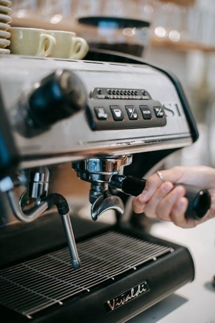
Pros of Automatic Coffee Machines
Automatic coffee machines excel in convenience and ease of use, requiring minimal user intervention․ They streamline the brewing process, often with programmable timers and automatic shut-off features, fitting seamlessly into busy lifestyles․ Consistency is another key advantage; these machines deliver reliably similar results each time, eliminating guesswork․
Furthermore, many models offer features like built-in grinders and milk frothers, expanding beverage options․ They reduce the learning curve associated with manual methods, making quality coffee accessible to everyone, regardless of experience․ This simplicity is a major draw for many coffee drinkers․
Convenience and Ease of Use
Automatic coffee machines prioritize user-friendliness, simplifying the coffee-making process significantly․ With just a few button presses, a fresh cup is ready, eliminating the need for precise measurements or manual techniques․ Programmable features, like automatic timers, allow users to wake up to freshly brewed coffee, enhancing daily routines․
These machines require minimal effort and skill, making them ideal for those seeking a quick and hassle-free coffee experience․ The straightforward operation reduces the learning curve, appealing to both novice and experienced coffee drinkers alike․ This ease of use is a primary benefit․
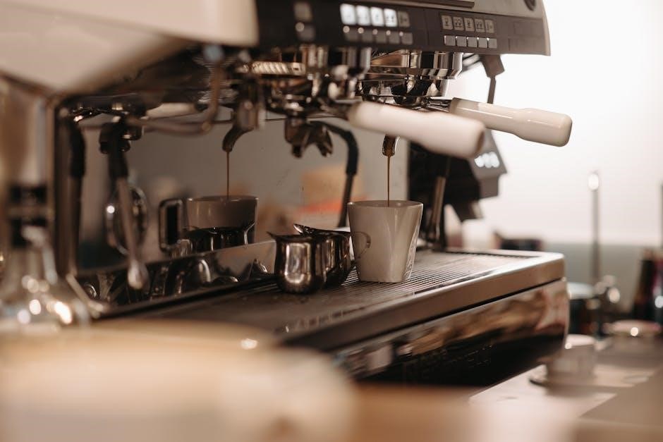
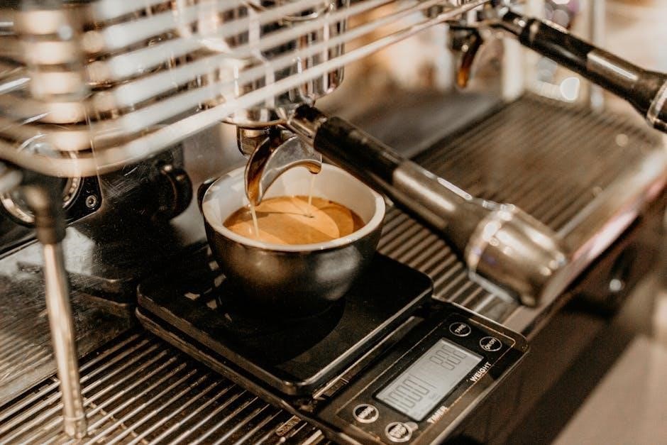
Consistency in Brewing
Automatic coffee machines excel at delivering consistent results, minimizing variations in taste and strength․ Pre-programmed settings and precise controls ensure each brew adheres to the same parameters, offering a reliable coffee experience every time․ This predictability is particularly valuable for those who appreciate a uniform cup of coffee without the need for constant adjustments․
Unlike manual methods, which rely heavily on user technique, automatic machines eliminate much of the human error, guaranteeing repeatable outcomes․ This consistency simplifies the process and provides peace of mind, knowing your coffee will taste as expected․
Cons of Automatic Coffee Machines
While convenient, automatic coffee machines often present limitations in customization, restricting users to pre-defined brewing parameters․ This can be frustrating for coffee enthusiasts who enjoy experimenting with grind size, water temperature, and brew time to achieve their ideal flavor profile․
Furthermore, certain automatic systems, particularly capsule or pod machines, can incur higher long-term costs due to the ongoing expense of proprietary consumables․ This contrasts with manual methods utilizing reusable filters and whole beans, potentially offering a more economical solution over time․
Limited Customization
Automatic coffee machines, prioritizing ease of use, frequently sacrifice the granular control offered by manual brewing․ Pre-programmed settings dictate parameters like water temperature and brew time, hindering experimentation for those seeking a personalized cup․
Enthusiasts often find themselves unable to adjust variables to suit different bean types or desired flavor profiles․ This lack of flexibility contrasts sharply with manual methods, where every aspect of the brewing process is directly managed by the user, allowing for precise adjustments and a truly tailored coffee experience․
Potential for Higher Long-Term Costs (Capsules)
Capsule-based automatic machines, while convenient, can incur significant long-term expenses․ The ongoing cost of purchasing proprietary capsules consistently exceeds the price of buying whole bean or ground coffee․
Although the initial machine cost might be lower, the recurring expenditure on capsules quickly adds up, making it a less economical choice for frequent coffee drinkers․ This contrasts with manual methods and even bean-to-cup machines, where coffee bean costs are generally more affordable, offering substantial savings over time․
Exploring Manual Coffee Machines
Manual brewing unlocks a world of flavor, demanding active participation and offering techniques like French Press, Pour Over, and lever espresso machines․
Popular Manual Brewing Methods
Several methods dominate the manual coffee landscape, each offering a unique experience․ The French Press, celebrated for its full-bodied brew, immerses grounds directly in hot water, requiring careful plunging․
Pour Over techniques, like V60 and Chemex, emphasize precision and control, allowing nuanced flavor extraction through slow, deliberate water flow․
For espresso enthusiasts, lever or piston-driven machines provide ultimate control over pressure and extraction time, mimicking professional barista techniques․ These methods demand skill and patience, but reward users with exceptional coffee quality and a deeper connection to the brewing process․
French Press
The French Press, a classic manual brewing method, delivers a rich and full-bodied coffee experience; It operates on the principle of immersion, steeping coffee grounds directly in hot water for a specified time․
This simplicity belies a degree of control; grind size, water temperature, and steep time all influence the final result․
After steeping, a mesh filter is slowly pressed down, separating the grounds from the brewed coffee․ The resulting brew often contains some sediment, contributing to its characteristic texture and robust flavor profile․ It’s a favored choice for those seeking a hands-on, flavorful cup․
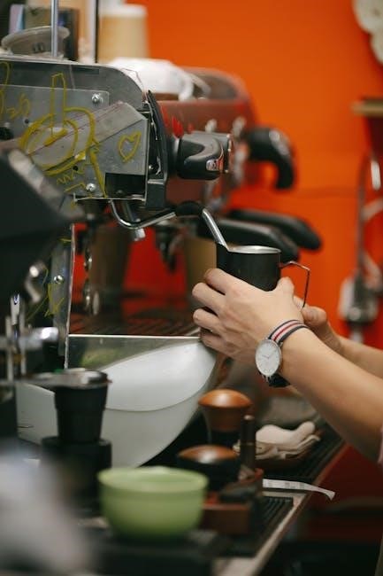
Pour Over (V60, Chemex)
Pour over methods, like those utilizing the V60 or Chemex, represent a refined manual brewing experience, emphasizing precision and control․ These techniques involve slowly pouring hot water over coffee grounds held within a filter-lined cone․
The rate of pour, water temperature, and grind size are crucial variables impacting extraction and flavor․
This method yields a clean, bright cup of coffee, highlighting the nuanced flavors of the beans․ It requires a bit of technique and patience, but rewards the user with a truly customized and aromatic brew․
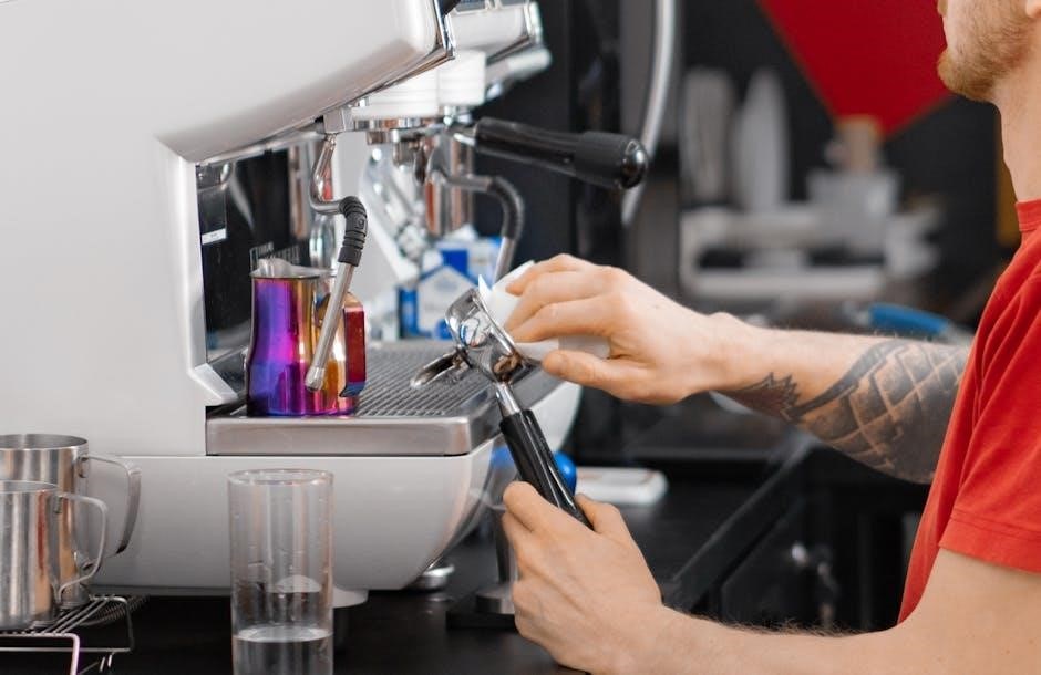
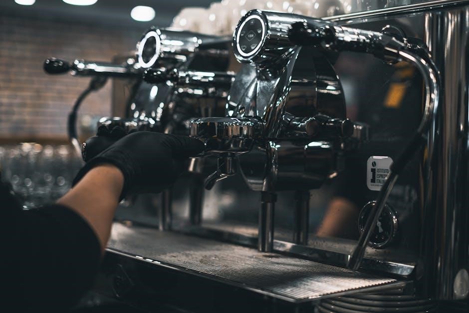
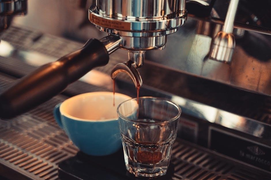
Espresso Machines (Lever/Piston)
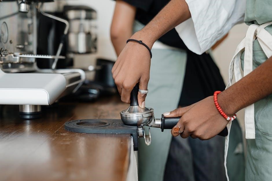
Manual espresso machines, often featuring lever or piston mechanisms, offer the ultimate control over the espresso-making process․ These machines require significant user input, demanding precise tamping, water temperature management, and pressure application․
The lever is pulled manually, forcing hot water through finely-ground coffee, creating a concentrated shot of espresso․
While demanding a steeper learning curve, these machines allow for unparalleled customization and the potential to extract the fullest flavor profile from the coffee beans, appealing to dedicated coffee enthusiasts․
Advantages of Manual Coffee Machines
Manual coffee machines empower users with a level of control unattainable with automatic counterparts․ This control extends to every aspect of the brewing process – grind size, water temperature, bloom time, and pour-over technique – allowing for precise adjustments to achieve a personalized flavor profile․
This hands-on approach often results in enhanced flavor potential, as skilled brewers can optimize extraction for their specific beans․
Furthermore, manual methods can be a more mindful and rewarding experience, connecting the brewer directly to the art of coffee making․
Greater Control Over Brewing Process
Manual brewing methods grant the user complete authority over critical brewing variables․ Unlike automatic machines with pre-programmed settings, techniques like pour-over or French press demand active participation and adjustment․
This includes precise control over water temperature, pour speed, bloom duration, and coffee-to-water ratio – all factors significantly impacting the final cup’s taste․
Experienced brewers can fine-tune these elements to highlight specific flavor notes and achieve optimal extraction, resulting in a truly customized coffee experience․
Enhanced Flavor Potential
Manual coffee brewing often unlocks a richer, more nuanced flavor profile compared to automatic methods․ The greater control afforded to the user allows for optimized extraction, revealing subtle aromas and complexities within the coffee beans․
Techniques like pour-over, for example, emphasize clarity and brightness, while a French press delivers a full-bodied, sediment-rich brew․
This ability to tailor the process to the specific bean origin and roast level allows enthusiasts to fully appreciate the coffee’s inherent qualities, resulting in a superior tasting experience․
Disadvantages of Manual Coffee Machines
While offering superior control, manual coffee machines present certain drawbacks․ A significant hurdle is the steeper learning curve; mastering techniques like pour-over or espresso extraction requires practice and understanding of brewing variables․
Furthermore, these methods demand considerably more time and effort than simply pressing a button on an automatic machine․
Consistency can also be a challenge, as slight variations in technique can impact the final result․ This makes achieving a reliably perfect cup more difficult for those seeking effortless brewing․
Steeper Learning Curve
Manual brewing isn’t as straightforward as pressing a button; it demands a commitment to learning the nuances of coffee extraction․ Techniques like the pour-over method require understanding grind size, water temperature, and pour rate to achieve optimal results․
Espresso machines, particularly lever or piston types, necessitate mastering tamping pressure and extraction time․
This initial investment in skill development can be daunting for beginners, requiring patience and experimentation before consistently producing high-quality coffee․
Requires More Time and Effort
Unlike the automated convenience of push-button machines, manual methods demand active participation throughout the brewing process․ Grinding beans, heating water, and carefully executing the brewing technique all contribute to a longer preparation time․
Each cup is a hands-on experience, requiring focused attention and effort․
This contrasts sharply with automatic machines that handle most steps independently, making manual brewing less suitable for those prioritizing speed and minimal involvement in their morning routine․
Cost Comparison: Initial Investment & Running Costs
Evaluating both upfront machine prices and ongoing expenses like coffee beans or capsules is crucial for determining the most economical brewing solution․
Automatic Machine Price Ranges
Automatic coffee machines exhibit a broad price spectrum, catering to diverse budgets and feature preferences․ Basic drip coffee makers, offering straightforward functionality, typically range from $30 to $100․ Stepping up, bean-to-cup machines, providing freshly ground coffee with automated processes, generally fall between $200 and $800, though high-end models can exceed $2,000․
Capsule or pod machines, known for their convenience, usually cost between $75 and $300․ However, it’s vital to factor in the recurring expense of capsules․ Premium automatic espresso machines, capable of replicating café-style beverages, can range from $500 to over $3,500, depending on features like dual boilers and integrated grinders․
Manual Machine Price Ranges
Manual coffee brewing methods generally present a more affordable entry point compared to automatic machines․ A simple French press can be acquired for as little as $20 to $50, offering a classic and immersive brewing experience․ Pour-over setups, including drippers like V60 or Chemex, typically range from $15 to $80, excluding the cost of filters․
For those seeking espresso, manual lever or piston machines start around $300 and can climb to $1,500 or more, depending on build quality and features․ These require significant skill and effort․ Ultimately, manual options prioritize investment in the brewing process itself, rather than automated convenience․
Cost of Coffee (Beans vs․ Capsules)
The ongoing cost of coffee significantly differs between automatic and manual systems․ Whole coffee beans generally offer the most economical long-term solution, with prices ranging from $10 to $25 per pound, depending on origin and quality․ This allows for greater control over quantity and freshness․
Capsule-based automatic machines, while convenient, often present a higher per-cup cost, typically between $0․50 to $1․00 per capsule․ This adds up quickly over time․ Manual brewing encourages bean purchases, fostering exploration of diverse flavors and potentially substantial savings compared to the recurring expense of proprietary capsules․
Maintenance and Cleaning
Automatic machines require descaling and regular cleaning cycles, while manual methods demand immediate rinsing of components to prevent residue buildup and maintain flavor․
Automatic Machine Maintenance
Maintaining automatic coffee machines generally involves regular descaling to remove mineral buildup, crucial for optimal performance and longevity․ Many models feature automated cleaning cycles, simplifying the process significantly․
Filters, both water and coffee, need periodic replacement, impacting brew quality․ Removable parts like drip trays and brew groups require frequent washing to prevent bacterial growth․ Neglecting maintenance can lead to decreased efficiency, altered coffee taste, and potential machine failure;
Following the manufacturer’s guidelines is essential, as specific models may have unique cleaning requirements․
Manual Machine Cleaning Requirements
Cleaning manual coffee machines demands more hands-on effort, varying by brewing method․ French presses require thorough rinsing and occasional deep cleaning to remove coffee oils․ Pour-over devices need regular washing to prevent residue buildup affecting flavor․
Espresso machines, particularly lever/piston types, necessitate backflushing to clear the group head and regular cleaning of portafilters and baskets․ Disassembling and cleaning components is often required․
Consistent cleaning is vital for optimal taste and hygiene, though it’s generally less complex than descaling automatic machines․
Ultimately, the best choice depends on balancing your desired coffee quality, available time, and willingness to learn brewing techniques․
Considering Your Coffee Preferences
Your ideal coffee profile should heavily influence your machine selection․ If you consistently crave simple, straightforward coffee, an automatic drip machine offers reliable convenience․ However, for espresso-based drinks or nuanced flavors, a manual espresso machine or pour-over method unlocks greater potential․
Those prioritizing speed and ease will likely favor automatic options, while coffee enthusiasts seeking control over variables like grind size, water temperature, and bloom time will appreciate manual brewing․ Consider if you enjoy experimenting with different beans and techniques – manual machines excel here․ Ultimately, aligning the machine with your taste preferences is paramount for a satisfying coffee experience․
Lifestyle and Time Commitment
Assess your daily routine and available time when choosing between automatic and manual coffee machines․ Automatic machines cater to busy lifestyles, delivering coffee with minimal effort – ideal for quick morning brews․ Manual methods, however, demand a more deliberate approach, requiring time for grinding, heating water, and careful brewing․
If you value convenience and speed above all else, an automatic machine is the clear choice․ But, if you enjoy the ritual of coffee making and have time to dedicate to the process, a manual machine offers a rewarding experience․ Consider your willingness to learn and practice brewing techniques․